Introduction
Designs created in an ECAD program may be electrically correct on the screen, but are ultimately constrained by the capabilities of your fabrication equipment. This tutorial walks through how to use the program DFM Now to verify that a design is able to be manufactured by the LPKF ProtoMat S63 in PRLTA 109.This tutorial requires that you have already exported Gerber files of your design from Cadence.
The following video shows the process described in this tutorial from start to finish.
Step 1: Install and Configure DFM Now
- Download and install DFM Now
- Download the Peralta Mill Specs.drf configuration file and save it to a known location. This file contains customized settings that will allow you to use DFM
Step 2: Run DFM Now on the Gerber Files
1. In Windows, launch DFM Now!2. Choose Import > AutoLoad (Gerber/Drill)..., select the folder that contains the Gerber and drill files for your project, and click Next (see Figures 1 and 2).
 |
| Figure 1: AutoLoad import menu |
 |
| Figure 2: Select Folder to Load window |
3. In the File Description: window (see Figure 3), choose the correct layer type for each layer. Common layer types include:
- Top Art = Top
- Bottom Art = Bottom
- Outline = Border (this is typically a graphic and may be the only one that you need to change)
- Soldermask Top = Mask Top
- Soldermask Bottom = Mask Bottom
- Drill = Drill ThruHole
 |
| Figure 3: File Description window |
4. Click Next and Finish.
5. Review your design and make sure all of the layers were loaded properly.
6. Choose DFM > DFM Rules Management... (see Figure 4). The DFM Check Settings window will appear (see Figure 5).
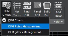 |
| Figure 4: DFM Rules Management menu selection |
 |
| Figure 5: Default DFM Check Settings window |
7. In the DFM Rules Settings window under Rules File Management, click Open... and choose the Peralta Mill Spec.drf file that is saved to your hard drive. Under Rules File Management, click Save As... and save the rules so they are available next time you open the program. New DFM settings will appear in the Signal tab (see Figure 6). Click Finish.
 |
| Figure 6: Custom Peralta Mill Spec DFM Rules Settings |
8. Choose DFM > DFM Check.... The General Settings window will appear (see Figure 7). Make sure that the DFM Rule Set is set to Peralta Mill Specs.drf and click Next to begin the design for manufacturing process.
 |
| Figure 7: General Settings window |
9. Depending on the complexity of your board, the DFM check will take several seconds to several minutes to run. If it uncovers any errors, you will need to find and correct them within PCB Editor, re-export your Gerber files, and re-run the DFM Check on the new Gerber files.
10. Once you have corrected all of the errors, you will receive a green checkmark. Success! (see Figure 8)
 |
| Figure 8: Example errors and success |
11. Bring your computer to a TA or professor during office hours and show them the results of your DFM check to receive approval for submitting your PCB design to Peralta for milling.
Based on a video and tutorial created by Robert Goby


Great explanation point to point it was so helped me to understand easily.
ReplyDeletedfm services